12 May 2026
Furby 2012 Motor Brush Repair
A practical repair for Furby 2012, Boom, and Crystal motors that are weak, noisy, stuck, or dead. The useful part of the original motor is usually still fine; the failure is often in the brushes. This keeps the original Furby motor body, shaft, and gearbox, then swaps in the better brush plate from a compatible donor motor.
Parts Used
- Original Furby 2012, Boom, or Crystal motor
- Compatible RK-30023-12370 / RF-300C style donor motor
- Soldering iron
- Small screwdriver
- Pliers or snips for the motor tabs
- A tiny amount of glue for the motor board
Before You Start
This starts after the motor is already out of the Furby. The delicate part is opening the motor and moving the brush plate without snapping the carbon brushes. Work slowly and keep the original shaft and gearbox intact.
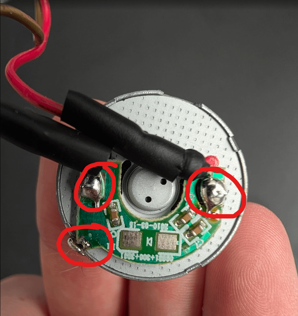
Desolder the motor board
Remove the small board and wires from the motor by desoldering the three marked points. Put the board somewhere safe; it goes back onto the repaired motor at the end.
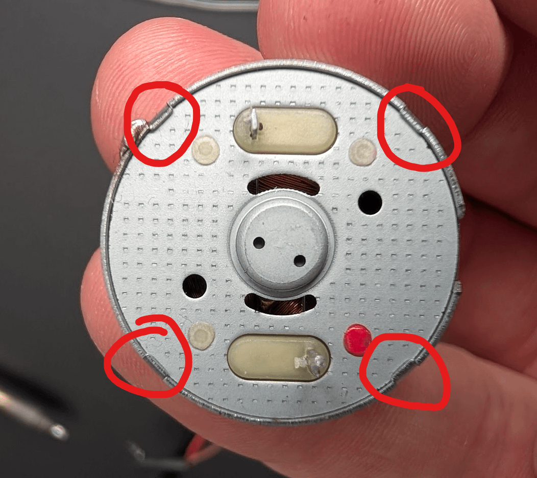
Open the original motor
Use pliers or snips to bend the four metal tabs away from the bottom plate. Once the tabs are clear, use the small hole in the plate to pry it open gently.
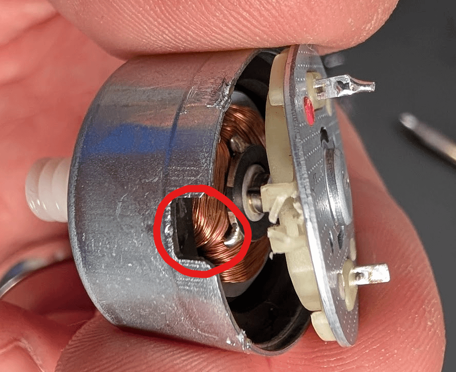
Check the failed brush
When the plate comes off, you can see why the motor has stopped behaving. In this example the brush is burnt and bent aside, so the motor can no longer make reliable contact.
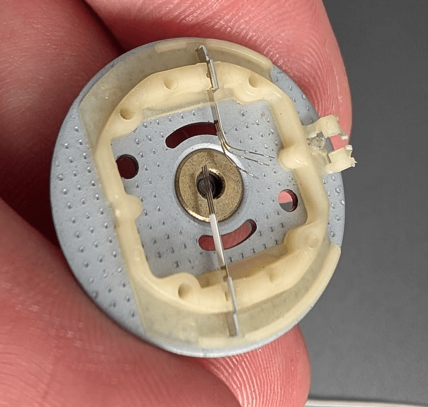
Open the donor motor
Open the black donor motor the same way. Keep its red and black wires attached because the donor plate does not have the same pins as the Furby motor.
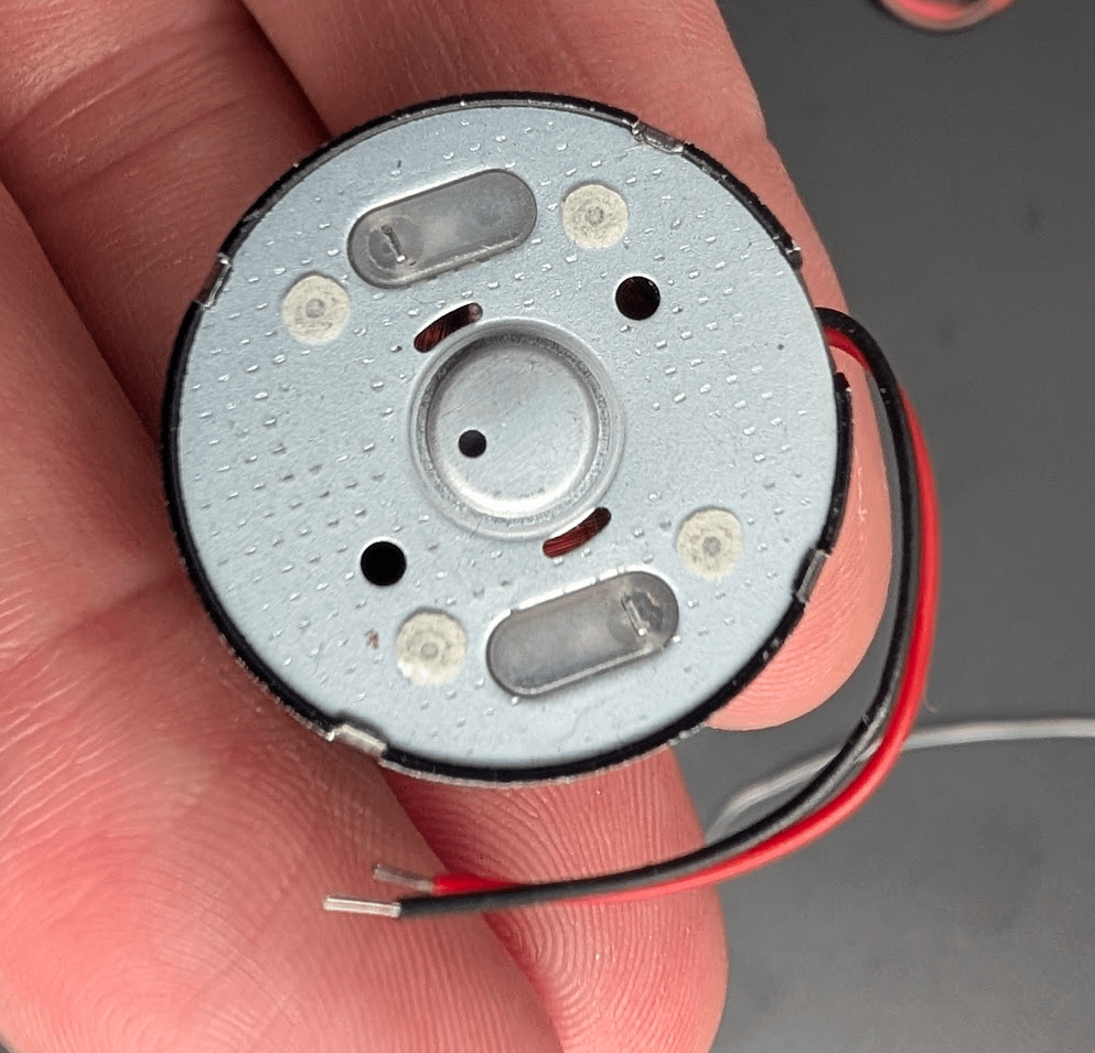
Move the donor brush plate
Take the donor bottom plate and brushes as one piece and fit them onto the original motor body. Come in at an angle and do not force it; the carbon brushes are the part you are trying to save.
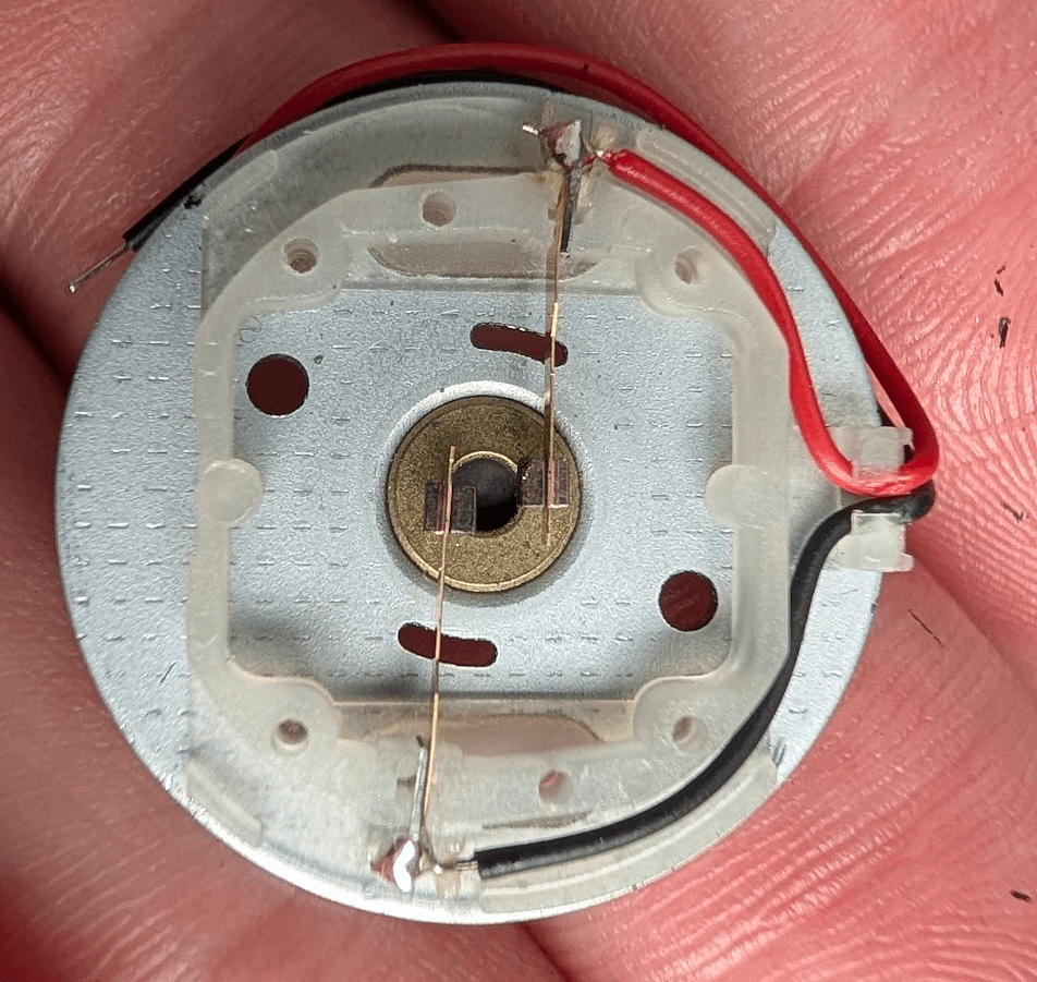
Seat the brushes
The brushes need to sit around the commutator cleanly. This sketch shows the idea: keep the brushes supported, then close the plate once they are correctly positioned.

Reattach the board and wires
Glue the small motor board back onto the bottom of the motor and solder the wires back on. The red wire goes to the side with two capacitors; the black wire goes to the side with one.
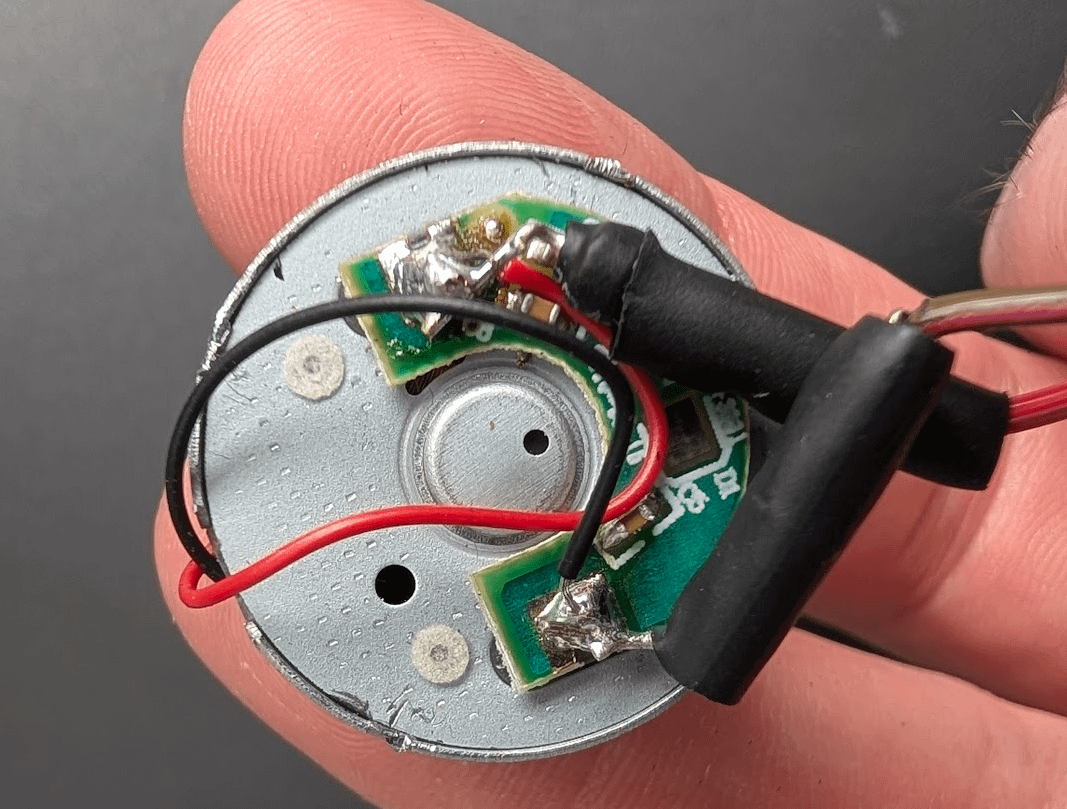
Source
This page is a local, cleaned-up version of my original Reddit guide, with the photos kept inline so the steps are usable.